 2-m
synthesized FM transceiver
2-m
synthesized FM transceiverI got my amateur radio license and the call DC1YB in 1970. Over the years, some homebrew devices were developed and created, and some of them were also built by other amateurs later (especially the synthesized FM radio and the pocket-sized 2-m mini radio), since they produce good results with a minimum of expense, and they use off-the-shelf parts only. Your prerequisites are a fine soldering iron, a few measurement tools, and, of course, some patience.
Hint for printing the circuit diagrams
If you intend to print a diagram, it is best to save the GIF image as a file
and to load it with an image editor or viewer later (like PaintShop, for
instance). Adapt the printing format to your paper size, possibly using
landscape orientation. In most cases, the browser itself does not create a
sophisticated printout.
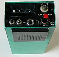
2-m
synthesized FM transceiverWhen designing portable radios, the main goal (besides a small size) is a low current drain. This device was among the first using a CMOS-based frequency synthesizer for the 2-m band from 144 to 146 MHz in 25-kHz steps, which results in 80 channels, and the battery current is only about 25 mA during reception.
Two of the four decimal switches are used for the receiver and the other two for the transmitter, so any repeater shift can be used.
Circuit diagrams: synthesizer (71 K), RX/TX (94 K)
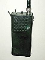 2-m
Mini - pocket-size FM transceiver
2-m
Mini - pocket-size FM transceiverThis pocket-sized FM radio uses a common 9-V block battery and drains only 10 mA during reception. Instead of a multi-channel synthesizer, 2 pairs of crystals are used for two fixed channels. The transmitter output is 100 mW, which is typically enough for a nearby repeater.
OE7NCI writes about this radio: "Inspite its only 70 mW, it saved the life of a female mountain climber. She and her partner were hit by a stone avalanche above 3000 m. She was injured at her head but I managed to get help with this little radio. The helicopter of the Austrian army came to that place in just about 20 minutes and used a winch to get down an emergency doctor and a mountain rescuer. She survived and could lesve the intensive care unit in Innsbruck after a few weeks for further treatment in Germany. That was in August 1978, and the story comes always to my mind when I see the little radio in the display case."
Diagram (GIF, 90 K)
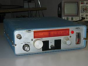 HF
receiver 300 kHz to 30 MHz
HF
receiver 300 kHz to 30 MHzIt is not a big deal to design a shortwave receiver for a limited frequency band, but this one is for 300 kHz to 30 MHz in one single range. Of course an additional fine tuning is used, so even CW and SSB stations can be decoded.
The concept is a triple-superheterodyne receiver with 50.7 MHz, 10.7 MHz and 455 kHz as intermediate frequencies, so cheap off-the-shelf filters can be used. The winding numbers in the diagram refer to a 6 mm plastic coil bobbin.
The first oscillator for 51 MHz to 80.7 MHz uses an air-isolated variable capacitor. Using newer technology, it could be replaced with a more stable crystal-controlled DDS module.
Diagram (GIF, 95 K)
Together with a few friends, a backpacking trip to Canada was planned, and we wanted to have a small-sized, battery-operated QRP transceiver for 20 meters. Even though a CW test is no longer necessary to get on HF, CW allows intercontinental connections with only one or two watts and a simple dipole antenna. The direct-conversion receiver uses an audio-based automatic gain control, an LC tone filter, and a 100-kHz crystal for frequency alignment. The same VFO is used for transmitting and receiving.
Diagram (GIF, 133 K)
 Speech
compressor with three transistors
Speech
compressor with three transistorsHere is a simple speech compressor with only three transistors. It often fits into the microphone case and controls the amplification with a time constant of about three seconds based on the speech level. In contrary to a typical clipper, it does not cause distortion or overdrive effects.
The first transistor is a voltage-controlled amplifier. The second one is used for an additional amplification with a slight preference for high-pitched audio frequencies. Short audio peaks are clipped by two diodes - one discrete and one formed by the base-emitter diode of the third transistor which is also used to control the bias of the first stage. (It is kind of suprising how many people say that they invented this circuit by themselves after I had published it in the German magazine Funkschau way back in 1975.)
Diagram (GIF, 12 K)
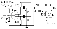
Even if you have a larger short-wave antenna, you typically connect it to a transceiver, so there is no aerial left for an additional receiver. Here is a simple FET-based active antenna circuit giving good results from 30 kHz to 30 MHz. A 75-cm steel rod or a telescopic aerial is used. The circuit must be directly at the bottom of the rod to avoid additional input capacitance. The supply voltage can be derived from the receiver in most cases. Since the circuit requires less than 10 mA, even a battery can be used for portable operation.
The active antenna is very linear. However, the receiver should have a good dynamic range or at least have a switchable attenuator to avoid intermodulation effects, since very loud signals can occur on the medium and short wave broadcast bands. With an AR5000 from AOR it was often possible to receive hamradio stations on 20 m which were weak on a G5RV antenna (unfortunately you cannot send over the active antenna!). You should place it far away from any interference sources like computers or TV sets and with a good ground connection at the antenna foot.
Sometimes it is nice to monitor the packet traffic on a frequency and write the QSOs between stations into different text files for later reviewing. I wrote an assembly-language MS-DOS program which only requires a dumb 1200-bps AFSK modem connected to a COM port, either with the TCM3105 or with the FX614 chip.
PRMON does all the AX.25 decoding by software. This is quite time-critical and requires direct access to the PC timer and RS232 chips, so it works under MS-DOS only, not in multitasking environments like Windows. However, it does sort of a multitasking itself, since it can be loaded as a TSR program (terminate and stay resident). So while it still runs in the background, you are already able to view the received text files in the foreground or at the DOS prompt.
The ZIP file contains the executable .com file and also the full 80x86 assembler source code. If you set a constant "english" to "true" while compiling, the resulting executable will be in English instead of German.
Download PRMON.ZIP (17 K)
 This
small-sized Morse program can decode and send telegraphy signals with any MS-DOS
PC, even on an Atari Portfolio handheld PC (see picture, only the tone
generation does not work on this machine). It also runs in a Windows 95/98 DOS
box, but not with Windows NT, 2000 or XP. I already had many HF CW QSOs using
this program, and none of my partners was aware that I was using a computer due
to the /S option which simulates natural manual keying.
This
small-sized Morse program can decode and send telegraphy signals with any MS-DOS
PC, even on an Atari Portfolio handheld PC (see picture, only the tone
generation does not work on this machine). It also runs in a Windows 95/98 DOS
box, but not with Windows NT, 2000 or XP. I already had many HF CW QSOs using
this program, and none of my partners was aware that I was using a computer due
to the /S option which simulates natural manual keying.
The DCD line of the PC's RS232 port must be connected to a tone decoder; -12 V is "no tone" and +12 V is "tone". The RTS line is used for keying the transmitter. The 2 K program does not require an extra receive/transmit switching and has a fairly good decoding ability. The function keys F1 to F9 control the transmit speed and also set a default decoding rate for reception. When you start CW.COM, you can use these commandline options (use /? to show all):
Commandline switches:
/1 to /4 = selects COM port 1 to 4
/N = do not use PC speaker for tones
/P = reverse tone decoder polarity at DCD line
/S = simulates manual keying by random variation
The ZIP file contains the executable .com file and also the full 80x86
assembler source code. If you set a constant "english" to "true" while
compiling, the resulting executable will be in English instead of German.
Download CW.ZIP (14 K)